

https://doi.org/10.3390/su14116559
”
The novel RPB included a rotor that consisted of stainless-steel packing and small holes mounted on the shaft as liquid injectors, which were expected to help distribution. The cavity zone was filled by packing to increase the contacting area in the rotor. NFs as solvents were injected with a nozzle into the center of the shaft and radially distributed in the packing to help cool the bearings. A gas stream was inserted circumferentially from the side of the casing (shell) into the center of the packing, made contact with the liquid droplets, and then left from via the housing.
As shown in Figure 2a, the setup used for CO2 capture included an RPB, an electromotor, a pump, a vessel of NFs, tubes, connections, pressure gauges, flow meters, and cylinders of CO2 and N2. The regeneration section of [64] was used in this study to generate the CO2-enriched stream.
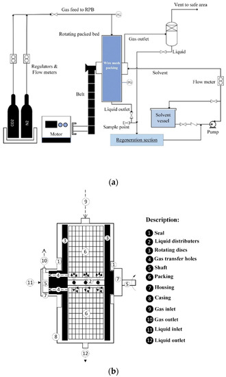
Figure 2. (a) Schematic of the experimental setup arrangement, (b) detail of the RPB.
After a leak test of the setup, test runs were performed by introducing gas from the top outside edge of the RPB casing, as shown in Figure 2b, which, after passing through the packing, exited the left housing from outlet gas holes. Simultaneously, the NF was injected into the rotor and distributed radially from small holes that were mounted on the shaft to make contact with the gas stream counter-currently. The gas outlet stream was sent to a safe location, and the liquid outlet was sent to the regeneration section. After the solvent was regenerated, it was recycled to the NF storage vessel. The sampling point for titration was at beginning of the liquid stream towards to the regeneration section.
The experiment steps for NFs included:
-
Introducing the mixed gas stream to the RPB under a flow control and design limitation of system, then venting it out to a safe location.
-
Turning on the RPB driver at low speed and checking the operating condition.
-
Turning on the solution pump, introducing the solvent to the RPB slowly, setting the operating conditions with the instrument devices, and keeping the proper situation (Table 3).
-
Starting the regeneration section and recycling the regenerated solution stream to the solution pump suction when a steady-state situation is reached, then closing the outlet of the solvent vessel and keeping the circulation circuit.
-
At this stage, the rotating speed can be changed when stability of the system is reached.
-
Sampling for titration is caried out after 10 min.
Table 3. Rotating packed bed specifications and conditions of the experimental runs.
| Packing Type | Stacked Layers of Wire Mesh |
|---|---|
| Inner diameter of rotor (shaft diameter), m | 0.035 |
| Outer diameter of rotor (disc diameter), m | 0.255 |
| Packing height, m | 0.034 |
| Total surface area (m2. m−3) | 563.04 |
| Surface tension of packing, mN/m | 75 |
| Porosity | 0.8958 |
| Rotational speed (rpm) | 300 & 500 |
| Liquid flow rate, L/hr | 24–42 |
| Gas flow rate, L/min | 6–16 |
| CO2 present range, % | 10–50 |
| Temperature, °C | 35 |
| Casing pressure, bar | 3.3 |
“According to Section 1, CO2 absorption was performed by NFs in the operating conditions given in Table 3—that is, above atmospheric pressure while considering the design condition of the RPB.
The RPB with stainless steel wire mesh packing shown in Figure 2b, which was used in this research, had a packing with a 0.0175, 0.1275, and 0.034 m inner radius, outer radius, and axial height, respectively.
The uncertainty errors of experimenting instruments and the maximum errors of parameters are given in Table 4 and Table 5, respectively.”
Table 4. Uncertainty of the instruments.
| Instrument Name | Instrument Range | Measured Variable | Accuracy | Min and Max Values Measured in Experiment | Uncertainty (U%) |
|---|---|---|---|---|---|
| Gas flow meter | 0–20 L/min | Volume flow rate of gas | 0.1 L/min | 6–16 L/min | 0.01–0.03 |
| Liquid flow meter | 0–200 L/h | Volume flow rate of liquid | 0.6 L/h | 24–42 L/h | 0.99–2.32 |
| Titration glassware | 0–50 ml | Volume of liquid | 0.1 mL | 0–30 ml | 0.15–10 |
| Thermometer | −200–850 °C | Inlet and casing temperatures | 0.1 °C | 30–35 °C | 0.44 |
| Scale | 0–300 g | Weight of NPs | 0.0001 g | 0.025–0.25 g | 0.05–0.15 |
Table 5. Uncertainty of the parameters.
| Variable | Uncertainty Error (U%) |
|---|---|
| kLa | 6.82 |
| ReL | 0.89 |
| ReG | 0.96 |
| We | 1.04 |
| Gr | 1.56 |
| Sc | 0.08 |
| kLadp/DL.at | 1.36 |
| ReNP | 1.10 |