https://doi.org/10.3390/coatings13020256
“The synthesis and characterization of fibrous materials with a hierarchical structure are of great importance for materials sciences. Among this class of materials, microfibers of different natures coated with carbon nanofibers attract special interest. Such coating modifies the surface of microfibers, makes it rougher, and thus strengthens its interaction with matrices being reinforced by the addition of these microfibers. In the present work, a series of hierarchical materials based on carbon microfibers, basalt microfibers, and fiberglass cloth coated with up to 50 wt% of carbon nanofibers was synthesized via the catalytic chemical vapor deposition technique. The initial items were impregnated with an aqueous solution of nickel nitrate and reduced in a hydrogen flow. Then, the catalytic chemical vapor deposition process using C2H4 or C2H4Cl2 as a carbon source was carried out. A simple and cost-effective technique for the preparation of the samples of hierarchical materials for transmission electron microscopy examination was developed and applied for the first time. The proposed method of sample preparation for sequential TEM visualization implies an ultrasonic treatment of up to four samples simultaneously under the same conditions by using a special sample holder. As was found, the relative strength of carbon nanofibers coating the surface of microfibers decreases in the order of CNF/CMF > CNF/BMF > CNF/FGC. Two effects of the ultrasonic action on the carbon coating were revealed. First, strongly bonded carbon nanofibers undergo significant breakage. Such behavior is typical for carbon and basalt microfibers. Secondly, carbon nanofibers can be completely detached from the microfiber surface, as was observed in the case of fiberglass cloth. In the case of CNF/CMF material, the graphitized surface of carbon microfiber is coherent with the structure of carbon nanofiber fragments grown on it, which explains the highest adhesion strength of the carbon nanolayer coated on carbon microfibers.”
”
2.3.2. Methodology of “TEM-Sonication” Studies
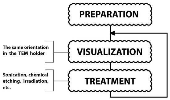
Conventionally, after the preparation procedure, which is designed to preserve the native morphology of the studied material, the sample is visualized using TEM and then discarded. The proposed alternative algorithm implies the following procedures: after the first visualization, the sample is removed from the microscope, and then undergoes some kind of treatment (sonication, irradiation, chemical etching, etc.) before being visualized with TEM again. In the present study, the sonication procedure was chosen for the treatment of synthesized hierarchical materials. Such a cycle can be repeated more than once (). It provides not only a normal TEM visualization of the samples, but also makes it possible to compare the adhesion strength between microfibers and CNF for a few samples (up to four at a time) simultaneously. Thus, the samples first visualized intact are then treated under the same conditions and visualized once again, thus allowing one to reveal the differences in the impact of the sonication on various hierarchical materials.
Figure 1. Procedure chart illustrating an approach used to examine the adhesion strength of CNF on the surface of microfibers.
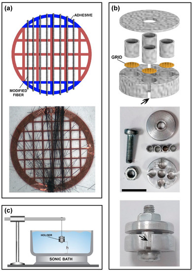
In order to provide the simultaneous treatment of a few TEM grids under identical conditions, a special metal holder was designed (b). When it is dipped into the water precisely above the center of the sonic bath, all the samples are placed at the same distance from the center of the bottom (source of ultrasonic waves) and thus sonicated at the same conditions. To avoid the effects of possible asymmetry, the holder can be rotated during the sonication procedure. The sonication intensity is adjusted by the distance between the bottom of the bath and the holder (c). After the sonication, the treated samples (TEM grids with glued microfibers, a) were dried out and examined with the TEM method once again.
Figure 2. Schematic representation of the procedures used for the preparation and treatment of the hierarchical samples: (a) attachment of the microfibers to a TEM grid; (b) assembling a holder for simultaneous treatment of four TEM grids (every slot has a notch to remove the grid using sharp tweezers (marked with the arrows), scale bar 10 mm); (c) sonication treatment of the holder (the distance from the bottom (h) can be varied to adjust the intensity of the treatment).
Note that in the case of conventional procedure used for visualization of damages or other surface changes, intact and treated samples are prepared independently using different TEM grids. Contrarily, the developed method provides an opportunity to visualize the same area of the microfiber’s surface with precision up to a single nanofiber before and after the treatment, thus revealing the fine structural aspects of the damage and comparing the behavior of all the samples under study.
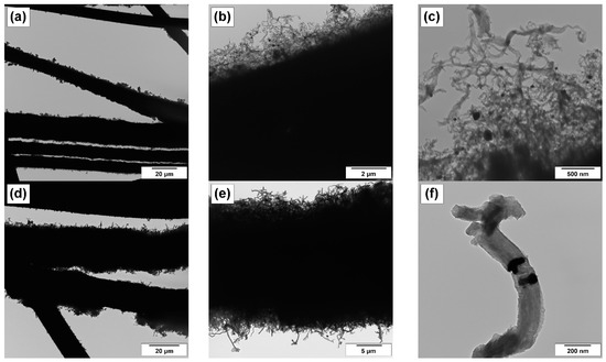
In order to explore the structure of the produced hierarchical materials in more detail, the more powerful TEM technique was used. In this research, the sample preparation method allowing one to fix the specimen of hierarchical material over the TEM copper grid has been proposed. The selected TEM images for the CNF/CMF (Y
C = 40 wt%) and CNF/BMF (Y
C = 50 wt%) samples are presented in . The general views shown in a,d indicate that all the microfibers are more or less coated with the CNF layer. The individual microfibers covered with the dense “forest” of carbon nanofibers can be seen in b,e. At last, the higher magnification (c,f) makes it possible to discern the carbon nanostructured filaments themselves as well as to observe the metallic nickel particles embedded into the structure of CNFs. The observed nickel crystals are responsible for the catalytic growth of carbon nanofibers, which is known to occur in accordance with the carbide cycle mechanism [
31].
Figure 4. TEM images of the pristine hierarchical samples: (a–c) CNF/CMF (YC = 40 wt%); (d–f) CNF/BMF (YC = 50 wt%). Active particles of metallic Ni catalyzing the growth of CNF are seen in TEM images (c,f).
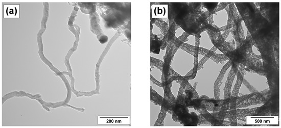
It is worth noting that the nature of the carbon precursor used in catalytic decomposition (C
2H
4 or C
2H
4Cl
2) affects noticeably the structural peculiarities of the grown carbon nanofibers. illustrates such an effect. It is seen that carbon filaments produced from ethylene (a) are thinner in diameter and better packed if compared with those obtained from 1,2-DCE (b). The presence of chlorine species in the reaction medium is known to be the key factor determining the formation of disordered carbon nanofibers with loose packing of graphene layers [
29,
32]. It might be expected that such “fluffy” filaments would be more fragile when subjected to further sonication or mechanical impact.
Figure 5. Effect of carbon precursor on the structure of CNFs: (a) CNF/CMF; (b) CNF/CMF(DCE).
3.2. Examination of the Adhesion Strength in Hierarchical Materials by TEM Technique Coupled with the Sonication Treatment
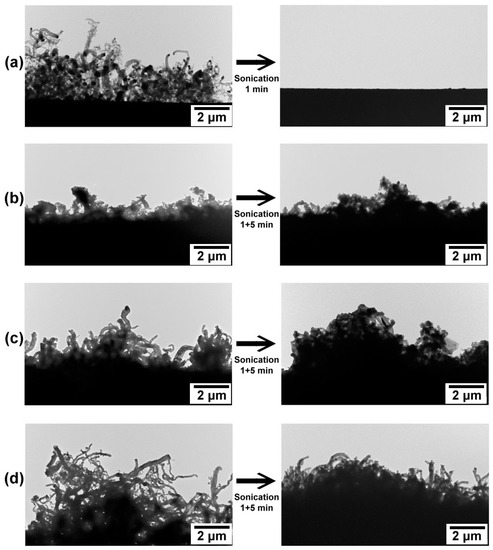
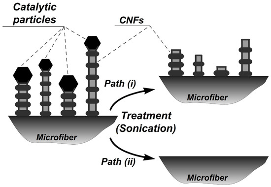
The four obtained samples of hierarchical materials (see ) were attached to the TEM grids and examined with TEM. Then, the grids were simultaneously sonicated at the same conditions (35 kHz, 50 W, 3 cm from the bottom of the sonic bath) for 1 min, dried at room temperature, and then examined with TEM again. In the next treatment experiment, the samples were sonicated for 5 min. The effect of the ultrasonic treatment is clearly seen in the TEM images (). Moreover, it is possible to distinguish different effects of sonication on the surface of the CNF-modified microfibers, such as breakage of CNF and their detachment from the surface of the microfibers. These effects are schematically illustrated in .
Figure 6. TEM images of the surface of modified microfibers before and after sonication treatment procedure: (a) CNF/FGC; (b), (c) CNF/CMF; (d) CNF/BMF. Note that the same areas of the fiber’s surface are compared.
Figure 7. Schematic illustration of different sonication effects, which can be distinguished by means of TEM visualization: path (i)—breakage of CNFs; path (ii)—detachment of CNF from the microfiber surface.
“