

https://doi.org/10.3390/su14074350
“A membrane contactor, having the advantages of a high surface area and high operational flexibility for ease of modularization, is a form of technology that has become a potential candidate for CO2 desorption [50]. The membrane contactor also possesses additional benefits as the gas and solvent have separate flow paths that can prevent foaming, flooding, entrainment, and channeling issues [51]. The membrane contactor technology has also been extensively studied by numerous researchers as it has the advantages of a large surface area for the mass transfer, it is lightweight, and has a small footprint for the system [52].
In the desorption process, the membrane is used as the non-selective barrier that is placed between two phases to keep these phases in contact and separated at the same time [53]. The selected gas is diffused to the permeate side through the membrane pores. Then, a sweep gas or steam sweeps out the CO2 gas on the permeate side to enhance the driving force for stripping the CO2. The steam is condensed to produce a high purity of CO2. Figure 4 illustrates the mechanism of the membrane contactor during solvent regeneration [54].
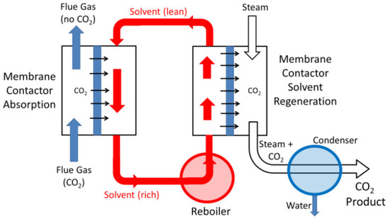
Figure 4. Membrane contractor configuration for separating and purifying CO2 [54].
The materials used in the membrane play an important role in controlling the efficiency of mass transfer for both the absorption and desorption of CO2 gas. The porous membrane contactor has been comprehensively studied for its property as a solvent absorption, and the CO2 is in direct contact with the pores of the membranes to facilitate the mass transfer. Nobuhide Takahashi et al. performed a study on the effect of membrane pore sizes towards the performance of CO2 desorption. Three different pore sizes, 0.2, 0.5, and 1.0 µm, of a microfiltration membrane (MF) were used to investigate the rate of CO2 desorption in 30 wt% monoethanolamine (MEA) solvent regeneration at a temperature of 40 °C. They found that the smallest membrane size (0.2 µm) has the highest rate of CO2 desorption, which is 4.6 × 10⁻⁶ m3/m2s for the pressure difference of 94 kPa, with a consideration of the volumetric flux as the desorption rate. The foaming phenomena was also recorded at this pressure difference. Additionally, the different membrane thicknesses produced the same trend as the pore size, as the rate of CO2 desorption increased with the increase in the membrane thickness, where a 2.9 mm membrane thickness with a pore diameter of 1.6 µm produced 450 × 10−6 m3/m2s of CO2 desorption rate [55]. It is crucial to maintain the permeate area at high pressures to avoid the steam from entering the solvent area due to the pressure difference. The phenomena causes the solvent to wet the membrane pores, which can lead to mass transfer reduction due to the slower diffusion rate [56,57,58,59,60,61].
As the porous membrane could lead to mass transfer reduction due to the wetted and foaming issues, several studies were conducted on non-porous membrane contactors, which, it is believed, could overcome this issue [62,63,64]. The non-porous membrane separates the gas and liquid phases, where the CO2 passes through the high permeate polymer as a gas [61,65,66]. Colin et al. performed the regeneration of MEA using a non-porous polydimethyl siloxane (PDMS) membrane. The study was carried out at a temperature range of 90–110 °C with a 20 kPa pressure difference and a 4µm membrane pore size. The highest temperature (110 °C) led to the highest mass transfer coefficient of CO2 to the permeate side, which was 0.3 cm/s, while the mass transfer coefficient of CO2 for the other temperatures mostly demonstrated a similar value of 0.01 cm/s [67].
Membrane contractors have a potential to be used in both absorption–desorption considerations, however the solvent selectivity for the separation should be good to avoid the membrane wettability and to reduce solvent degradation for long-term applications. This hybrid pressure-driven technique requires absorbent regeneration to occur in a continuous mode of absorption processes in series or parallel configurations [68,69]. The process offers the potential of a reduction in the energy regeneration in the series case and capital costs in the parallel case. The membrane contactor permits the mass transfer from a liquid phase to a gas phase, or vice versa for the gas–liquid membrane separation. The separation occurs through the membrane due to the driving force generated by the difference of partial pressure or difference of concentration at both sides of the membrane. Forcing the dispersed phase through the membrane created a constant quantity of droplets that produced uniform emulsions. This phenomenon could reduce the energy input as well as the wall shear stress to the membrane [70]. Witchipan et al. performed a modeling study to analyze the energy requirement for CO2 desorption from a CH4 solvent. It was reported that the combination of the membrane contactor with a slightly vacuum condition on the permeate side could provide a high-net energy, which is 0.178 MJ/m3. The value of this net energy is equivalent to the 85.37% reduction from the total energy required to generate up to 90% of CH4 regeneration from the CO2-rich solvent [71].
The membrane contactor has been recognized to provide a better mass transfer due to the large contact area, compared to the conventional process. Additionally, the membrane contactor provides 500 times more contact area than the liquid–liquid extraction column, and 30 times more compared to the gas absorber [72]. Normally, a conventional packed-bed column provides an active interfacial area between 100 to 250 m2/m3. The hollow fiber membrane could covert the same value of interfacial area with the compact size in the design. However, the usage of the membrane contactor faces some constraints. Firstly, the gas and liquid flow is constrained by the pressure drop coming from the packing density of the fiber membrane. Secondly, the porosity of the membrane could reduce the mass transfer area due to the occurrence of a chemical reaction within the boundary layer [54].
Karl Anders Hoff et al. performed modeling work to study the size reduction in the membrane contactor, compared to the packed column in the absorption–desorption cycle process [73]. Figure 5 shows the potential of a membrane contactor to replace the absorber and desorber unit for the typical gas treatment system. The rectangular modules were used for the post-combustion capture with a dimension of width, length, and depth were 3 m, 3 m, and 1 m, respectively, while the high pressure modules are used for the gas treatment with a 2-to-2.5 m maximum diameter and a 5 m maximum length. They found that the total volume of the separator is reduced by 75%, compared to the conventional absorber and desorber tower. The overall size reduction obtained from the modeling results is shown in Table 1.
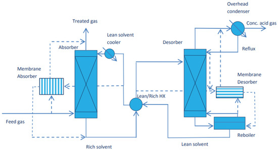
Figure 5. Simplified absorption and desorption processes that have the potential to be replaced with a membrane contactor system [73].
Table 1. Adaptation from the simulation results of the membrane contactor vs. packed tower [73].
| Scenario | Post-Combustion Capture | Natural Gas Treatment | Natural Gas Treatment with the Presence of Promoter |
|---|---|---|---|
| Solvent used | 30% MEA | 30% MDEA | 30% MDEA 5% piperazine |
| Liquid flow mode | Shell side | Shell side | Shell side |
| Fiber length (meter) | 3 | 5 | 5 |
| Total packed volume (m3) | 675 | 52 | 113 |
| Volume reduction | 75% | 75% | 54% |
“