

https://doi.org/10.3390/en12132504
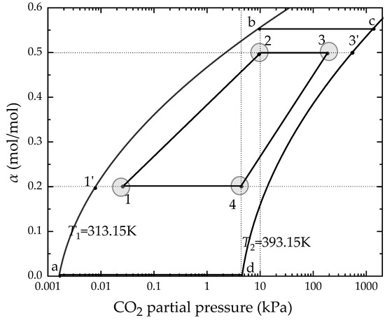
“An ideal four-step chemical amine-based cycle is drawn in an isothermal equilibrium curves diagram as given in Figure 4. Before the configuration, there are some assumptions to simplify the ideal cycle:
-
The absorption and the desorption are set to an isothermal process.
-
During the pre-heating and cooling process, the CO2 loading remains unchanged, that is, no CO2 desorption occurs.
-
The absorption and the desorption process are in a gas–liquid equilibrium state.
-
All kinds of heat loss in the cycle are not considered.
-
The solution does not react with other types of gases in the flue gas except CO2, and the flue gas is assumed to be an ideal gas.
As shown in Figure 3, the ideal cycle implies the reaction time is infinitely long and the performance of the absorbent is too ideal. At the same time, it indicates the ideal energy efficiency that the actual cycle can never reach, which is also not easy to compare with other models. Therefore, combined with the actual performance of the MEA solution and other practical constraints, the lean and rich solvent loading were set to 0.2 mol/mol and 0.50 mol/mol, respectively. Within the constraints of the carbon source and carbon sink, this ensures the state points 2 and 4, the driving force, Rabs and Rdes, and a condition parameter will be used to describe the how close the actual partial pressure is with the equilibrium partial pressure in the absorption and desorption process, which are defined as Equation (5) and Equation (6):
where Rabs and Rdes are the partial pressure ratios for absorption and desorption; P′1 and P′3 are the equilibrium CO2 partial pressure of lean and rich solvent; and P1 and P3 are the CO2 partial pressure of the inlet of the absorber and the inlet of the desorber.
“