

https://doi.org/10.3390/en15020425
”
It is important to establish the capital cost contributions of the different functional operational units, to show why attention needs to be given to the cost reduction of lean/rich heat exchangers. This is a common practice when the EDF method is employed for the capital cost estimation of a process plant [35]. It helps during the process development because the process engineer can see the effect of their choices very quickly. In addition, it becomes easier to communicate between the cost estimator and the process developer on which equipment needs to be cost optimised [35].
Figure 3 and Figure 4 present the capital cost distribution of the CO2 capture plant for the NGCC power plant’s exhaust gas and the cement plant’s flue gas, respectively. If any of the three shell and tube heat exchanger types are employed as the lean/rich heat exchanger, then the lean/rich heat exchanger becomes the second- and third-highest contributing equipment to the total plant cost in the standard cases of the cement plant and NGCC power plant capture processes, respectively. The cross-exchanger contributes 16% or 17% if FTS-STHX or FH-STHX, respectively, is selected for its function in the two standard CO2 capture and compression processes. Nwaoha et al. [14] showed that broadly specified STHX calculated the cross-exchanger contribution in an MEA capture process from a cement plant flue gas to be 17%, which is the same value estimated for the FH-STHX case in this study. This study applied the same overall heat transfer coefficient as [14]. The lean vapour compression configuration reduced the lean/rich heat exchanger’s contribution to 10% in both FTS-STHX and FH-STHX cases and in both the NGCC power plant and the cement flue gas treatment processes. This is because of a reduction in steam requirement by the reboiler due to the extra stripping vapour supplied to the desorber in this case. If PHE is used instead of any of the STHXs, the cross-exchanger will only contribute 5% and 3% to the TPC in both standard and lean vapour compression CO2 capture plant configurations, respectively, in two different industrial processes.

Figure 3. Capital cost distribution of 90% CO2 standard capture plant and lean vapour compression plant for the 400 MW NGCC power plant’s exhaust gas.
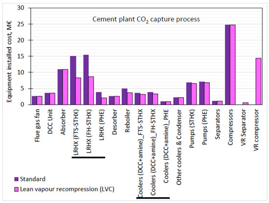
Figure 4. Capital cost distribution of 90% CO2 standard capture plant and lean vapour compression plant for cement plant’s flue gas.
Since the same type of heat exchanger was specified for the cross-exchanger, lean MEA cooler and DCC cooler functions, in the NGCC power plant’s case, the total plant cost will decline by 14% and 9% for the standard configuration and the lean vapour compression configuration, respectively, in comparison with the reference case (FTS-STHX). In the cement plant’s case, the reduction in TPC is 17% and 10%, respectively. These results for the base cases show a significant cost reduction in the TPC.
In the NGCC power plant cases, the absorber contributes the highest amount to the TPC. That is, 42–44% and 31–34% in the standard model and the lean vapour compression configuration, respectively. Meanwhile, in the cement plant’s cases, the contributions are 14–17% and 13–14% in the standard model and the lean vapour compression configuration, respectively. This is low due to the relatively lower volume flow of flue gas and higher CO2 partial pressure due to the higher CO2 concentration in this case compared to the power plant’s case. The absorber dimensioning results for both systems are presented in Table 8. In the case of the NGCC power plant, the absorber was split up into three units since for diameters greater than 10 m, concrete columns are a better choice, and stainless steel was specified in this study [46].
Table 8. Absorber dimensioning data.
| Absorber | |||
|---|---|---|---|
| Unit | NGCC Process | Cement Plant Process | |
| Number of units | – | 3 | 1 |
| Shell tangent-to-tangent height | m | 40 | 40 |
| Diameter (overall) | m | 16.32 | 6.50 |
| Diameter per unit | m | 9.43 | 6.50 |
| Stages | – | 29 | 17 |
| Packing height | m | 17.4 | 17 |
| Packing type | – | Structured packing (MellaPak 250Y) | Structured packing (MellaPak 250Y) |
“